ER-16 Headstock and Motor Unit

The 3308 would replace the standard headstock, motor and speed control assembly that come on Sherline machines.
The ER-16 nut that ships with your order may be plain or have a black oxide finish.

SKU: 3308
  • *Preferred unit of measurement for laser engraved portions
    Please note that our ball screws only come in a metric pitch

Product Description

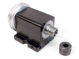
ER-16 Spindle Available

Note that the headstock, DC motor and speed control can also be ordered with an ER-16 collet spindle nose in place of the standard Sherline #1 Morse internal taper and 3/4-16 thread on the nose for those who prefer to use ER-16 collets. Sherline does not supply the collets, but they are available through MSC Industrial Supply Co. and other tool suppliers. Keep in mind that if the ER-16 nose is ordered, no Sherline accessories that use a #1 Morse taper or 3/4-16 thread will work on this spindle.

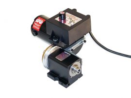
To power, and control the motor a more sophisticated speed control unit is required. This unit accepts any incoming AC current from 100 VAC to 240 VAC, 50 or 60 Hz and automatically outputs 90V DC to the motor, so this unit can be used anywhere in the world without a transformer. All you need is the correct wall plug or converter. Once the on/off switch is switched to the “ON” position, a speed control knob is used to vary the speed over the entire range. With the pulley in the “normal” position, the speed range is about 70 to 2800 RPM. In the “high torque” position the maximum speed is cut in half but torque at any given speed is much greater.

This unit can be purchased to replace an existing AC/DC motor on an older Sherline machine, to turn a mill XYZ base into a complete mill so that you don’t have to swap power units back and forth from the lathe, or as a stand-alone unit for custom tooling designs. This very compact and well-engineered unit costs far less than other DC units of similar power offered in major industrial tool supply catalogs.

ER-16 Collet Range Specifications

Inch Metric
.020″ – .393″ .5 mm – 13 mm

warning-symbol
The improper use of machine tools and their accessories can result in serious injury. Before using this tool, thoroughly read the instructions and make sure you understand its proper and safe use.

safety-glasses-symbol

Always wear safety glasses when operating machine tools.

Download PDF DC Motor Instructions

Instructions PDF Download

Download PDF DC Motor Wiring Instructions

Instructions PDF Download

SPINDLE
Headstock spindle bore .406″
Headstock spindle nose internal taper 16° taper
Headstock spindle external thread 22 x 1.5 mm
Pulley groove side angle 19°
ALLOWABLE TOLERANCES
Spindle Runout (at spindle nose), Maximum allowable (Most are within .0005″) 0.001″
Spindle End Play (adjustable with preload nut), Factory Settings with 2800 RPM Pulleys: 0.0002″with 10,000 RPM Pulleys: 0.0003″
HEADSTOCK BEARINGS
Designation/stock number (ZZ refers to “double shielded”) 6004ZZ
Size of bore 20 mm (0.7874″)
Tolerance of bore 0.0004″
Outside Diameter 42 mm (1.6535″)
Tolerance of OD 0.0005″
Width 12 mm (0.4724″)
Bearings 9 balls, 1/4″ Dia.
Motor and Speed Control ELECTRIC MOTOR SPECIFICATIONS FROM MANUFACTURER
Type of enclosure Totally enclosed, non-vented
Duty rating Continuous–10 oz. in. at 6100 rpm, .85 amperes; Intermittent–30 oz. in. at 5500 rpm, 1.75 amperes (5 minutes on / 15 minutes off)
Output horsepower .06 KW (60 W) at 10 oz. in. / 6100 rpm
AC voltage (input) Normally 115 VAC, 60 Hz, Single Phase to rectifier (Sherline electronic speed control converts any input from 100 VAC to 240 VAC, 50-60 Hz.)
DC voltage 90V DC to motor (60 Hz)
Speed in rpm 6100 rpm continuous
Class of insulation Class A, 105° (C.) insulation system
Normal full load current .85 amperes
Starting current 1.7 amperes instantaneous starting current (<100 milliamperes). This is also stall current in True RMS
Max current at time of changeover from lower speed to higher speed Depends on load
Type of motor 3.00 inch (outer diameter) sub-fractional horsepower brush-type permanent magnet motor
Temperature rise at ambient 50° C. Less than or equal to 45° C.
Motor frame size 3 inches
End use of motor Drive unit for lathe or mill
30111 ER-16 Headstock Assembly
33050 DC Motor & Speed Control Assembly
40020 Motor Bracket
40040 Drive Belt
  1. To view .igs files you need an IGS viewer. CLICK HERE to download a FREE IGS viewer.
  2. To view .stp files you need an STP viewer. CLICK HERE to use Autodesk’s FREE A360* online file viewer. STP is a file extension for a 3-D graphic file used by CAD software. STP stands for STandard for the Exchange of Product model data. STP files are used to store 3D image data in an ASCII format, following the standards defined in ISO 10303-21: Clear Text Encoding of the Exchange Structure.
  3. Each 3D file format has been compressed into a .zip file to save file space. Click on the .zip file link below to download it to your computer.
  4. Extract the .zip file to the drive location of your choice.
  5. Open the .igs file using the IGS Viewer, or open the .stp file using the A360 Autodesk online viewer.

*NOTE: There are also other free STP viewers that can be downloaded directly to your computer.

ER-16 Headstock 3D files

CLICK HERE to download the 3D IGS file
CLICK HERE to download the 3D STP file

ER-16 Collet Nut 3D files

CLICK HERE to download the 3D IGS file
CLICK HERE to download the 3D STP file

If you are working with brass or wood, we suggest you use the toggle switch dust cover to protect the life of your motor & speed control.