Purpose of the Sherline Mill XYZ Bases
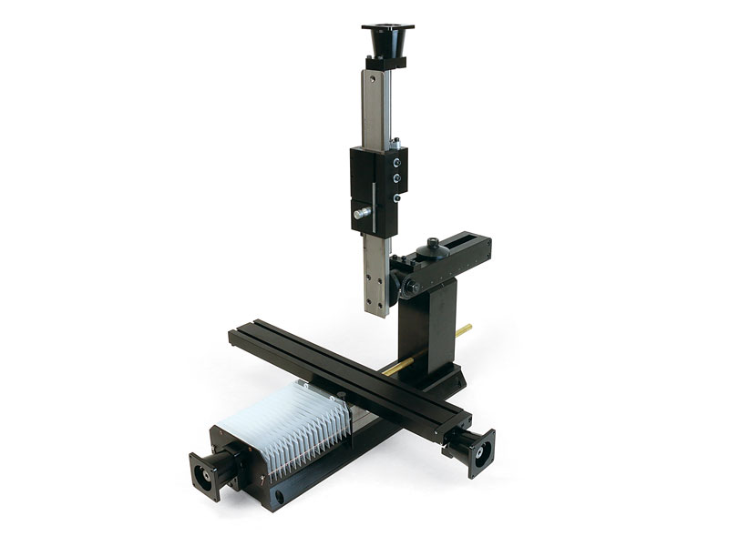
The Sherline ball screw mills can be purchased without the headstock and motor/speed control. This allows owners of other Sherline machines to swap the headstock and motor/speed control from one machine to the ball screw mill in approximately 60 seconds. This package offers a savings compared to the price of our full ball screw mills.
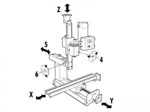
The Axes of Movement of a Sherline 6858 Ball Screw Mill
The table left/right movement is referred to as the X-axis. The table in/out movement is the Y-axis. Headstock up/down movement is referred to as the Z axis. The headstock can also be rotated on its saddle on Sherline mills (#4), the column ram can be moved in and out (#5), and the Z-axis column can be tilted forward and back (#6).
Standard equipment for the 685801 XYZ base:
- 18″ Mill Base
- Electroless nickel/Teflon coated mill saddle
- 15″ Extended Column Bed with nickel/Teflon plating
- Extra-Rigid Column Base
- 18″ Extended Mill Table
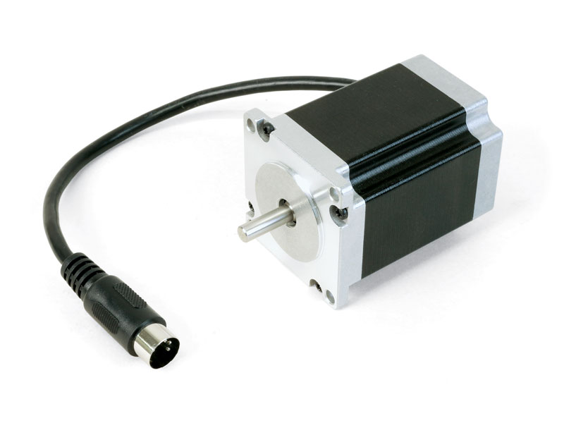
- Stepper-motor mounts with high-torque couplings
- The handwheels are included and can be mounted to the end of the stepper motors to maintain manual control when needed.* 2-1/2″ (63mm) adjustable “zero” handwheel on the Z-axis and 2″ (51mm) adjustable “zero” handwheels on the X- and Y-axes. Each handwheel has laser engraved aluminum handwheel collars
*NOTE: CNC-ready machines cannot be operated manually unless double-shaft stepper motors are installed. - Oil reservoirs on the X/Y axes and the Z-axis to help keep critical parts lubricated.
- Brass leadscrew cover that keeps chips off the rear of the Y-axis leadscrew
- Accordion way cover
- Travel: X=13.65″ (347 mm), Y= 11.0″ (279 mm), Z=9.25″ (235 mm)


