14″ Deluxe 8-direction Milling Machine

SKU: N/A
  • *Preferred unit of measurement for laser engraved portions
    Please note that our ball screws only come in a metric pitch
    Reset options

Product Description

The deluxe 8-direction milling machine offers the most versatility of any Sherline mill. In addition to X-axis, Y-axis, and Z-axis travels, there are five additional directions that the headstock spindle can be positioned to do drilling or milling on your part from virtually any angle. The headstock can pivot up to 90° in either direction. The column bed can be rotated side-to-side up to 90° in either direction for angled drilling. A special knuckle allows the column to be pivoted front to rear. The “ram” design of the column base also allows the entire ram to be pivoted up to 90° side-to-side. Loosening the column cap allows the ram to be moved in and out with over 5.5″ of travel.

With this many directions of movement, the machining possibilities are virtually limitless withing the size capabilities of the machine. The 14″ long base also increases Y-axis travel by an additional 2″ compared to the Model 5400 mill. This is the mill for those who want to take their miniature machining abilities to the extremes.

Notes on ordering a metric mill

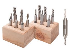
Most of our cutting tools, like center drills, are manufactured in a fractional size. If you have a metric machine with metric holders, like collets or end mill holders, you will need to order fractional holders to accommodate our cutting tools.

Standard equipment for the model 2000 (2010 metric) mill includes:

  • A powerful 90V DC motor with electronic speed controller
  • 14″ base
  • 2-1/2″ (63mm) adjustable “zero” handwheel on the Z-axis and 2″ (51mm) adjustable “zero” handwheels on the X- and Y-axes
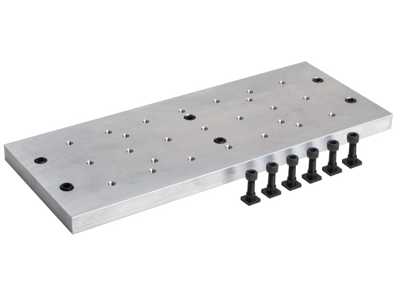
  • 2.75″ (70 mm) x 13.0″ (330 mm) table with two T-slots
  • ¼” Drill Chuck w/ key, #1 Morse arbor with drawbolt
  • 2″ column riser block
  • Laser-engraved scales on the base and table
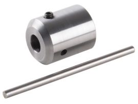
  • Pulleys, drive belt, three hexagonal keys, spindle bars, gib removal tool, eight-foot three-wire power cord, and instruction manual
  • Oil reservoirs on the X/Y axes and the Z axis to help keep critical parts lubricated. These were initially developed for CNC machines that run constantly for hours on end but can benefit manual machines as well
  • Brass leadscrew cover that keeps chips off the rear of the Y-axis leadscrew

warning-symbol
The improper use of machine tools and their accessories can result in serious injury. Before using this tool, thoroughly read the instructions and make sure you understand its proper and safe use.

safety-glasses-symbol

Always wear safety glasses when operating machine tools.

Download PDF Assembly and Instruction Guide

Instructions PDF Download

Download PDF 2000/2010 Mill Set-up Instructions

Instructions PDF Download

2000-series Mill Z-axis Installation instructions

Instructions PDF Download

Download PDF 14″ Mill Base Dimensions

Instructions PDF Download

Download PDF Mill Saddle Lubrication instructions

Instructions PDF Download

Max clearance
(table to spindle)
9.00″ (229 mm)
Throat
(no spacer)
Adjustable
Throat
(w/ headstock spacer)
Adjustable
Travel, “X” Axis 8.65″ (220 mm)
Travel, “Y” Axis 7.00″ (178 mm)
Travel, “Z” Axis 5.38″ (137 mm)
Hole through spindle .405″ (10 mm)
Spindle nose thread 3/4″-16 T.P.I.
Spindle nose taper #1 Morse
Spindle runout of Morse taper .0005″ or less
Handwheel graduations .001″ (.01 mm)
Electronically controlled spindle speed range 70 to 2800 RPM
Width Overall* 15.00″ (381 mm)
Depth Overall* Base footprint: 16.625″ (422 mm); With fully extended brass leadscrew cover: 20.625″ (524 mm)
Height Overall (Max.)* 23.38″ (568 mm)
Table size 2.75″ x 13.00″ (70 x 330 mm)
Hold-down provision 2 T-Slots
Shipping Weight 45 lb. (20.1 kg)
Movements in addition
to X-, Y- and Z-axes
Headstock rotation (90° left/right)
Column rotation (90° left/right)
Column pivot (90° forward/back)
Column swing (90° left/right)
Column travel (in/out) 5.5″ (140 mm)
Motor 90 volt DC with electronic speed control that accepts any incoming current from 100VAC to 240 VAC, 50 Hz or 60 Hz.

Click here for motor specifications
Spindle Speed Range 70-2800 RPM continuously variable by electronic speed control

*Overall dimensions include motor and speed control

Click on the link for the exploded view of the 2000/2010 Mill to help identify replacement parts.

If you are still uncertain please call our customer service representatives for help with this item.

Click the P/Ns below to download a zipped version of the IGS 3D CAD file. You will need to extract the zip file before viewing the files.
2000 3D IGS model
You need an IGS viewer to open .igs files. CLICK HERE to download a FREE IGS viewer.

Shipping

We do not charge a flat rate for shipping because of the variations in weight for our products. Instead, we charge you what the shipping company charges us. Our website uses a shipping calculator based on the daily rates for USPS and UPS based on the weight and destination of the shipment. You can also have us use your UPS/FedEx account number to charge your shipping. Just enter it in the appropriate box on the checkout page.

Domestic orders are shipped Monday – Friday. Expedited orders must be placed by 9 am PST to ship the same day.

Orders shipping ground have a processing time of 7 working days for domestic orders and 14 working days for international orders. CLICK HERE for more information on our shipping and order policies.

Returns

Most merchandise can be returned within 30 days of the purchase date. A refund will be issued to the original form of payment at the original selling price. View our complete return policy and/or start your return online here.