18″ NexGen Mill – CNC Ready

NexGen Vertical  Milling Machine (18″ base) + CNC-Ready stepper motor mounts.

SKU: N/A Tag:
  • *Preferred unit of measurement for laser engraved portions
    Please note that our ball screws only come in a metric pitch
    Reset options

Product Description

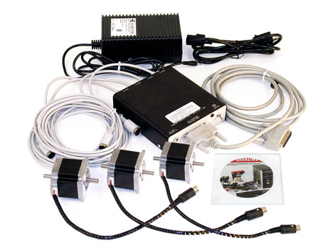
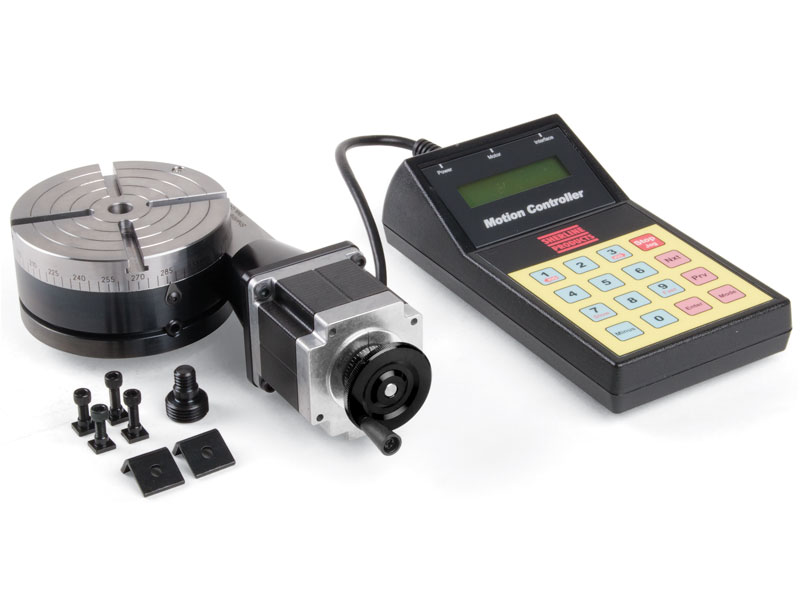
Any Sherline mill can be ordered with stepper motor mounts factory installed in place of the handwheels and ready for the application of stepper motors and computer numeric controls (CNC). Sherline supplies the mounts, and several aftermarket suppliers offer motors, drivers and software to complete the CNC system. You supply the 486 or better computer. See our CNC Dealers page for a list of supplies and links to their home pages.

Sherline recommends using dual shaft stepper motors so that handwheels can be applied to the rear shaft for manual control. With that in mind, handwheels for each axis are included with the machine, although they cannot be used until stepper motors are installed. Sherline also offers high-quality stepper motors, which can be found in the accessories section of this site.

Notes on ordering a metric mill

Most of our cutting tools, like center drills, are manufactured in a fractional size. If you have a metric machine with metric holders, like collets or end mill holders, you will need to order fractional holders to accommodate our cutting tools.

Standard equipment for the mill includes:

  • A powerful 90V DC motor with electronic speed controller
  • 18″ mill base with Y-axis leadscrew protection
  • 2.75″ (70 mm) x 18.0″ (457 mm) extended mill table with two T-slots
  • 7″ x 13″ tooling plate
  • 15″ (63mm) extended column bed
  • Extra-rigid column base
  • The handwheels are included and can be mounted to the end of the stepper motors to maintain manual control when needed.* 2-1/2″ (63mm) adjustable “zero” handwheel on the Z-axis and 2″ (51mm) adjustable “zero” handwheels on the X- and Y-axes. Each handwheel has laser engraved aluminum handwheel collars
    *NOTE: CNC-ready machines cannot be operated manually until stepper motors are installed.
  • ¼” Drill Chuck w/ key, #1 Morse arbor with drawbolt
  • Oil reservoirs on the X-, Y- and Z-axes
  • Pulleys, drive belt, three hexagonal keys, spindle bars, gib removal tool, eight-foot three-wire power cord, and instruction manual

warning-symbol
The improper use of machine tools and their accessories can result in serious injury. Before using this tool, thoroughly read the instructions and make sure you understand its proper and safe use.

safety-glasses-symbol

Always wear safety glasses when operating machine tools.

Download PDF Assembly and Instruction Guide

Instructions PDF Download

Download PDF 18″ Mill Base Dimensions

Instructions PDF Download

Download PDF Mill Saddle Lubrication instructions

Instructions PDF Download

Max clearance
(table to spindle)
14.00″ (356 mm)
Throat
(no spacer)
Adjustable
Throat
(w/ headstock spacer)
Adjustable
Travel, “X” Axis 13.65″ (347 mm)
Travel, “Y” Axis 11 ″ (279 mm); 8.9″ (226 mm) with tooling plate attached
Travel, “Z” Axis 5.38″ (137 mm)
Hole through spindle .405″ (10 mm)
Spindle nose thread 3/4″-16 T.P.I.
Spindle nose taper #1 Morse
Handwheel graduations .001″ (.01 mm)
Electronically controlled spindle speed range 70 to 2800 RPM
Width Overall 20.00 (508 mm)
Depth Overall Base footprint: 20.625″ (524 mm); With fully extended brass leadscrew cover: 27.875″ (708 mm)
Height Overall (Max.) 24.50″ (622 mm)
Table size 2.75″ x 18.00″ (70 x 457 mm)
Hold-down provision 3 T-Slots
Shipping Weight 50 lb. (22.7 kg)
Movements in addition to X-, Y- and Z-axes Headstock rotation 90° left/right
Column pivot 90° forward/back
Column swing 90° left/right
Column travel (in/out) 5.5″ (140 mm)
Motor 90 volt DC with electronic speed control that accepts any incoming current from 100VAC to 240 VAC, 50 Hz or 60 Hz. Click here for motor specifications
Spindle Speed Range 70-2800 RPM continuously variable by electronic speed control

*Overall dimensions include motor and speed control

Click on the link for the exploded view of the 5800-CNC/5810-CNC CNC-Ready Mill to help identify replacement parts.

If you are still uncertain please call our customer service representatives for help with this item.

Shipping

We do not charge a flat rate for shipping because of the variations in weight for our products. Instead, we charge you what the shipping company charges us. Our website uses a shipping calculator based on the daily rates for USPS and UPS based on the weight and destination of the shipment. You can also have us use your UPS/FedEx account number to charge your shipping. Just enter it in the appropriate box on the checkout page.

Domestic orders are shipped Monday – Friday. Expedited orders must be placed by 9 am PST to ship the same day.

Orders shipping ground have a processing time of 7 working days for domestic orders and 14 working days for international orders. CLICK HERE for more information on our shipping and order policies.

Returns

Most merchandise can be returned within 30 days of the purchase date. A refund will be issued to the original form of payment at the original selling price. View our complete return policy and/or start your return online here.