Product Description
About the Horizontal Milling Conversion

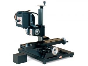
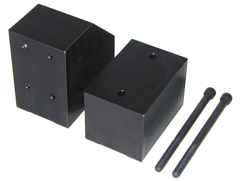
The horizontal milling conversion allows the mill column to be repositioned in two different ways on a sturdy base plate in order to provide greater versatility in set-up and increase the machinable area of the parts being worked on. To the left of the mill is the base of the Z-axis column, which has been cut off to allow a lower positioning of the headstock in relation to the table.
An easy way to increase the size of work that can be machined on your Sherline 5000- or 5400-series mill is the addition of the horizontal milling conversion. By allowing the vertical column to be mounted in various positions in relation to the table, and with the headstock and spindle rotated 90° into the horizontal position, a tremendous variety of machining possibilities are opened up. Plus, the mill can remain mounted to the conversion base and still operate in its conventional vertical mode as well, providing a very sturdy and vibration-free base.
With the work mounted perpendicular to the table, position “A” allows an area of up to 9″ by 6″ to be machined without moving the work—a very large work area for a machine of this size! (The 90° angle plate, #3559 can be very useful for this purpose.) A second set of holes allows the spindle to be moved further back so longer tools such as drills or a boring tool can be used. In position “B”, the table is reversed and the column rotated 90° to the table to take advantage of the long X-axis travel (which becomes the Y-axis in this configuration). This position could offer an advantage when drilling a deep hole, for example.
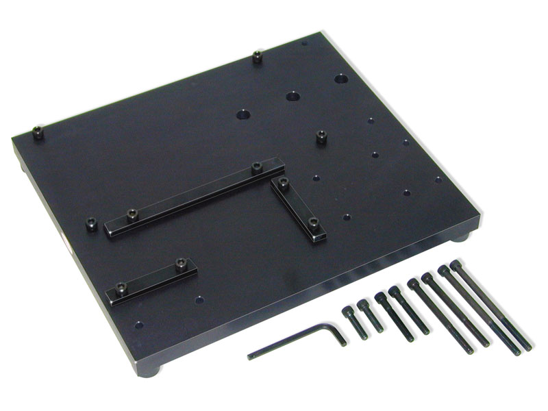
The base is 3/4″ thick aluminum 10.5″ by 12.5″ and is machined and drilled to accept the base on your mill’s vertical column. The headstock is rotated 90°, and the unit is remounted to predrilled holes in various positions on the conversion plate. The mill’s vertical column base should be modified by cutting off 2″ from its height to lower the spindle in relation to the table. (Machines made prior to 1993 will also require a 90° keyway on the Saddle.) This allows the spindle center to go below the top of the table, meaning you can machine the edge of material overhanging the table. The cutoff piece from the column is machined flat and re-tapped to be used as a spacer block to return the mill to its normal height.
* Instructions are provided for you to make this modification yourself if you already have a cutoff saw and a mill you can use, or we can make the modification for you if you return your vertical column to us. The modification is listed as P/N 6101. Please call for instructions on how to return your column base.
Alignment bars are provided with the conversion so that once the base and column are mounted and squared up, they can be quickly and accurately remounted in the future. Alignment bars, a hex wrench, and all necessary fasteners are provided to set up the mill in all of the possible configurations. The plate is mounted on four rubber feet for quiet operation. Complete instructions are provided.


